Retro3D Toolkit: Curves On Curves Documentation
Welcome to the Curves On Curves panel of the Retro3D Toolkit within Blender. This specialized panel offers innovative tools and features designed to empower artists, developers, and programmers with an affinity for retro 3D graphics. By facilitating advanced control over the interaction between curves during the mesh generation process, this panel simplifies the creation of complex, curve-based models, ensuring both efficiency and a high degree of artistic freedom.
Getting Started with Curves On Curves
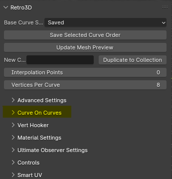
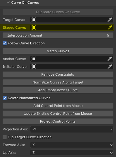
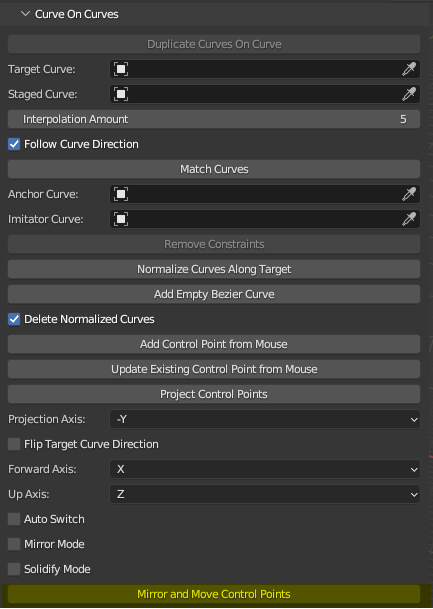
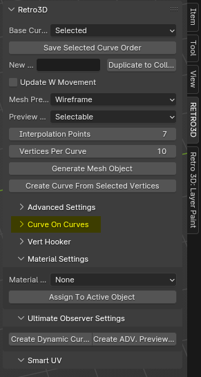
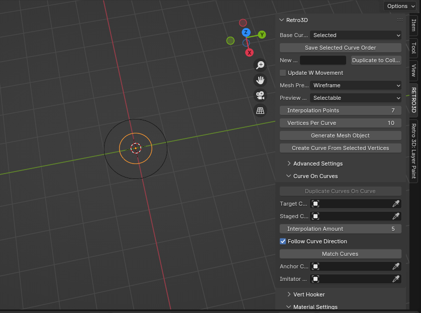
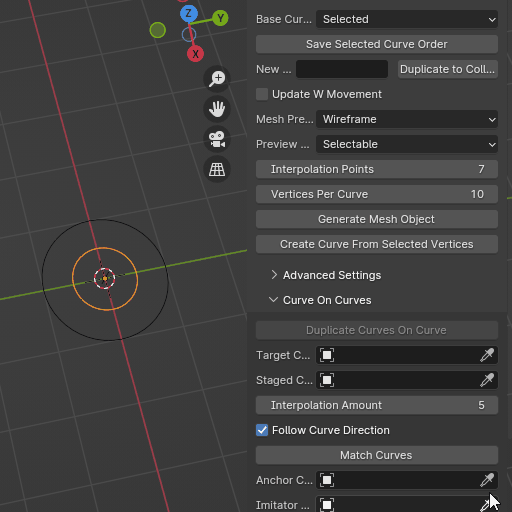
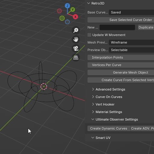
The Curves On Curves panel is seamlessly integrated into Blender's 3D Viewport UI, categorized under 'RETRO3D'. It's an extension of the main Retro3D settings, allowing for deeper customization and manipulation of curves within your projects. Highlighted below in yellow is the panel for these features.
Accessing the Panel
- Open Blender and navigate to the 3D Viewport.
- Locate the 'RETRO3D' tab on the UI sidebar to reveal the Retro3D Toolkit options.
- Click on Curve On Curves to expand the panel and access its features.
Features Overview
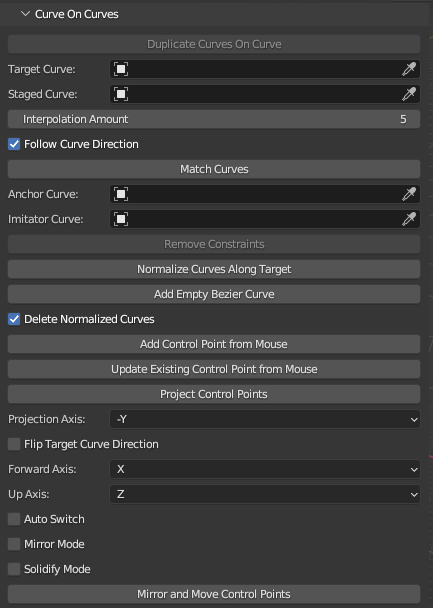
The panel is equipped with a range of options for duplicating and manipulating curves. Key features include:
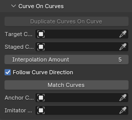
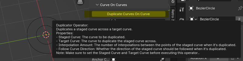
Duplicate Curves On Curve
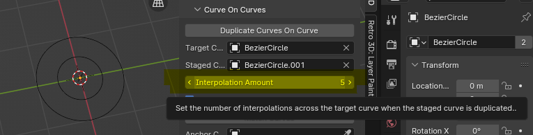
- Functionality: Creates duplicates of a 'staged curve' along a 'target curve', allowing for intricate patterns and designs. This is similar to an array modifier with the exception that we automatically setup follow constraints to aid in the mesh generation process.
- Use Case: Ideal for creating repeated patterns or distributing objects along a path in a non-linear fashion.
Target Curve
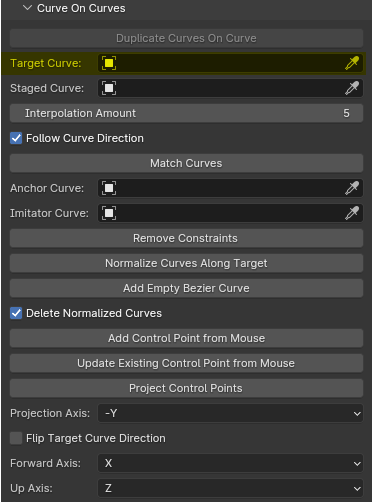
- Description: The curve along which the 'staged curve' will be duplicated.
- Usage: Select the curve object you wish to use as a path for duplication.
Staged Curve
- Description: The curve to be duplicated along the 'target curve'.
- Usage: Choose the curve object you want to replicate along the path defined by the target curve.
Interpolation Amount
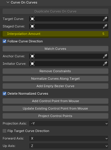
- Description: Controls the density of the duplicated curves along the target curve.
- Usage: Adjust to increase or decrease the number of duplicates, allowing for tighter or more spread out distributions.
- Tip: Use Odd numbers for guaranteed control point at center of curve.
Follow Curve Direction
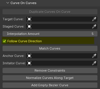
- Description: Determines whether the duplicated curves will align with the direction of the target curve.
- Usage: Toggle on to maintain directional consistency, enhancing the natural flow of your designs.
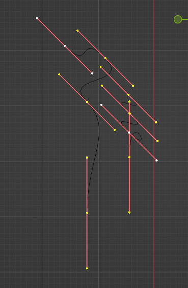
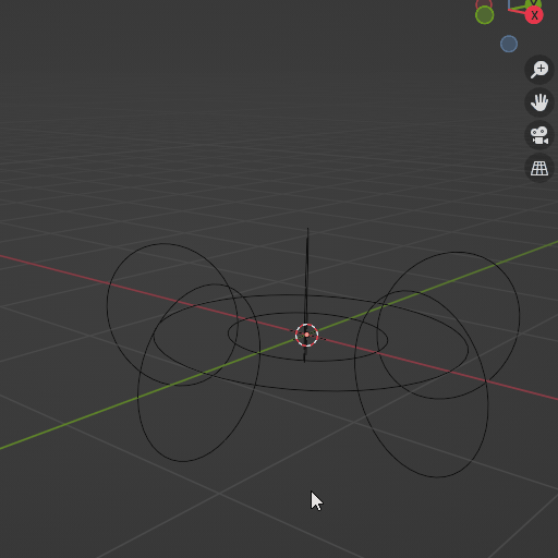
- Example: Following a circle along a jagged curve can give us easy "Longbows". In this case we first draw the core shape of the mesh we are creating and then allow the interpolated curves to further refine our goal. This immediately already provides a more interesting starting shape, by defining the core "curve" or "shape" of the center of mass first and then building around that with curves, gives us incredibly quick results and far more control from an iterative standpoint when attempting to make variations as opposed to directly modifying vertices and edges and faces directly.
Match Curves
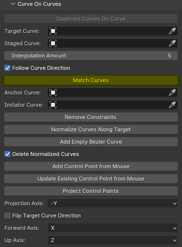
- Functionality: Aligns two curves by modifying one to match the shape and orientation of the other.
- Use Case: Useful for creating symmetrical designs or ensuring continuity between different sections of a model. Also great for in the event that a core curve that is controlling other constrained objects, requires extensive modifications of the control points, one can simply make the edits and then transfer the data into a different curve.
Anchor Curve
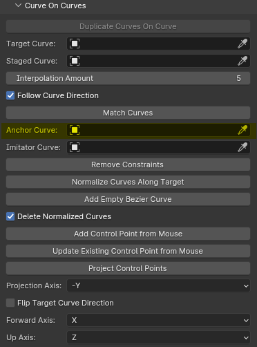
- Description: The curve that serves as the reference for matching.
- Usage: Select the curve you wish to remain unchanged, acting as the template for alignment.
Imitator Curve
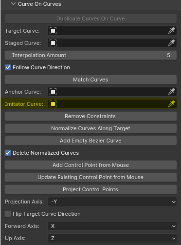
- Description: The curve that will be adjusted to match the anchor curve.
- Usage: Choose the curve that needs to be modified to achieve symmetry or continuity.
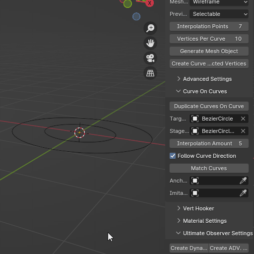
Normalize Curves Along Target
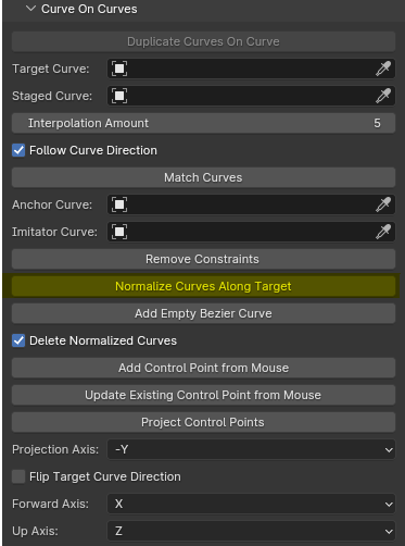
This will take the curves from the "Saved" selection and then "Normalize" them accordingly to the length of the Target Curve. This is especially useful for a 2D to 3D conversion workflow when needing to get the base curves propagated along the target curve to being further refining the shape of the object after initializing it in 2D.
Create Empty Curve
This is designed for the 2D to 3D pipeline, this creates an empty curve, with no control points, ready to be used in conjunction with the draw curves tool to draw a new curve worry free. This will be added to the collection of the selected collection or the collection of the active object selected.
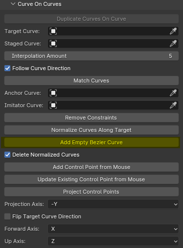
Delete Normalized Curves
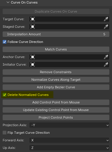
When enabled, will automatically delete the curve collection being duplicated along the target curve ( mostly used in 2D to 3D workflow). This is great for cleaning up the mess you made behind you as you move through your project.
Add Control Point From Mouse ( Raycast )
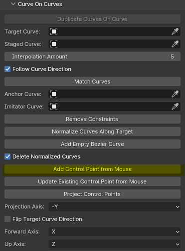
- Description: Adds a new control point to the selected curve at the position of the mouse cursor in the 3D viewport via Raycast.
- Usage: With a curve selected and in EDIT mode, enable this option and left-click in the 3D viewport to add a control point at the desired location. This allows for quick and intuitive editing of curves directly in the viewport.
Tip
Use this feature to add fine details or make local adjustments to your curves without needing to switch to edit mode. This is powerful when combined with our Create Empty Curve
Update Existing Control Point From Mouse
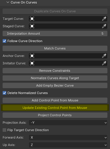
- Description: Updates the position of the selected control point on the selected curve to the mouse cursor's location in the 3D viewport.
- Usage: With a curve selected, enable this option and left-click near an existing control point in the 3D viewport. The nearest control point will snap to the mouse cursor's position, allowing for quick adjustments and refinements.
Tip
This feature is particularly useful when making small, precise changes to the shape of your curves, as it eliminates the need to manually select and reposition individual control points. This is great for cleanup after projection techniques.
Project Control Points
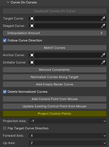
- Description: Projects the control points of the selected curve onto a plane perpendicular to the axis specified by the "Projection Axis" setting, while maintaining the curve's 3D position.
- Usage: With a curve selected, click the "Project Control Points" button to flatten the curve's control points onto a plane based on the chosen projection axis. This operation modifies the positions of the control points relative to the plane, but preserves the overall 3D location of the curve. Must be in EDIT mode and should only project the selected control points.
Tip
Use this operator to simplify complex 3D curves by reducing their dimensionality along a specific axis. This can be helpful when working with curves that need to be constrained to a certain plane or when preparing curves for specific modeling or animation tasks. By combining this operator with the "Projection Axis" setting, you can quickly create planar variations of 3D curves relationally to other 3D objects to suit your design needs.
Projection Axis
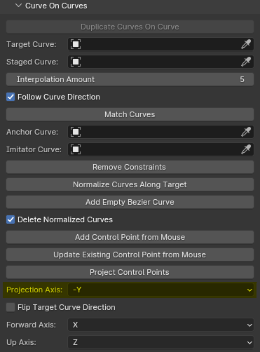
- Description: Determines the axis along which the entire curve will be projected.
- Usage: Select the desired axis (X, Y, Z, -X, -Y, or -Z) to flatten the curve onto a plane perpendicular to the chosen axis. This is useful for creating 2D projections of 3D curves or for simplifying complex curves for certain applications.
Tip
Use this feature in conjunction with other tools to create unique 2D designs from 3D curves, or to prepare curves for use in other software that may require planar input.
Flip Target Curve Direction
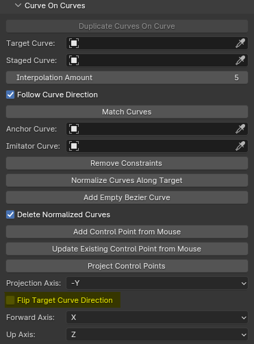
- Description: Determines the direction in which the duplicated curves are placed along the target curve.
- Usage: When enabled, the duplicated curves will be placed starting from the opposite end of the target curve compared to the default direction. This allows for more control over the orientation and layout of the duplicated curves.
Tip
Use this option to create mirrored or reversed patterns along the target curve, or to ensure the duplicated curves align with specific features or requirements of your design.
Forward Axis
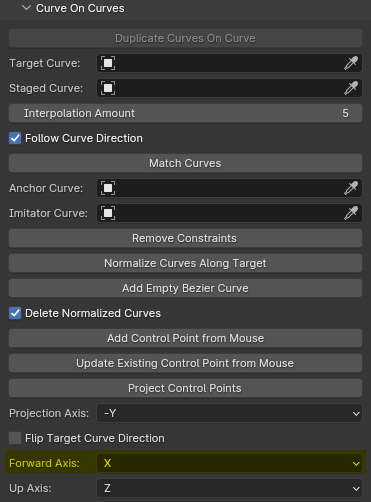
- Description: Sets the axis that determines the forward direction for the follow path constraint.
- Usage: Choose the axis (X, Y, Z, -X, -Y, or -Z) that represents the forward direction for the duplicated curves as they follow the target curve. This setting affects how the duplicated curves orient themselves along the path.
Tip
Adjust the forward axis to control the orientation of the duplicated curves relative to the target curve, ensuring they align with the desired direction of your design.
Up Axis
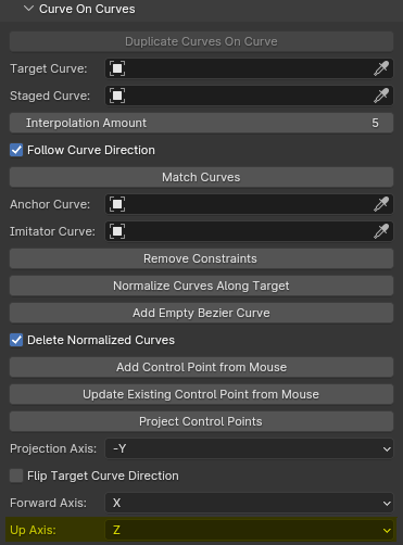
- Description: Defines the axis that determines the up direction for the follow path constraint.
- Usage: Select the axis (X, Y, or Z) that represents the up direction for the duplicated curves as they follow the target curve. This setting helps maintain the correct orientation of the duplicated curves relative to the path.
Tip
Use the up axis in conjunction with the forward axis to precisely control the orientation of the duplicated curves, ensuring they maintain the desired alignment along the target curve.
Auto Switch
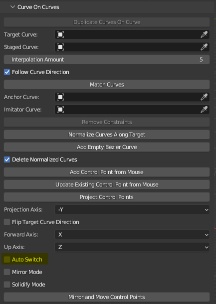
- Description: When enabled, automatically selects the current Collection in the base preview collection to be the newly created one.
- Usage: Enable this option to streamline your workflow by automatically updating the selected Collection to the most recently created one. This is particularly useful for forward-moving pipelines where you want to focus on the latest additions to your project.
Tip
Use Auto Switch to minimize manual selection steps and keep your focus on the creative process, ensuring that you're always working with the most up-to-date Collection.
Mirror Mode
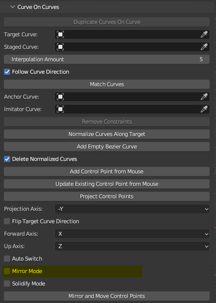
- Description: When enabled, automatically adds a Mirror modifier to the newly created mesh preview object.
- Usage: Enable Mirror Mode to quickly create symmetrical meshes based on your curve inputs. This feature applies a Mirror modifier to the generated mesh preview, allowing you to work on one half of the object while the other half is automatically mirrored.
Tip
Use Mirror Mode to speed up the modeling process for symmetrical objects, reducing the need for manual duplication and alignment of geometry.
Solidify Mode
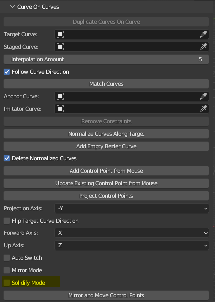
- Description: When enabled, automatically adds a Solidify modifier to the newly created mesh preview object.
- Usage: Enable Solidify Mode to give thickness to your generated mesh previews. This feature applies a Solidify modifier to the mesh, allowing you to create solid objects from your curve-based designs easily.
- Customization: You can adjust the following properties of the Solidify modifier:
thickness: Controls the thickness of the solidified mesh. Adjust this value to achieve the desired thickness.offset: Determines the offset distance of the solidified mesh from the original mesh. Use this to control the position of the solidified geometry.use_even_offset: When enabled, ensures that the thickness is applied evenly on both sides of the mesh.use_quality_normals: When enabled, improves the quality of the normals for the solidified mesh, resulting in smoother shading.
Tip
Use Solidify Mode in combination with other modifiers and tools to create more complex and detailed 3D models, starting from simple curve inputs. Experiment with different thickness and offset values to achieve the desired visual effect.
Mirror And Move Control Points
- Description: Takes all currently selected control point curves, moves them 2 units across the negative Y-axis, and connects them to form a loop.
- Usage: With a set of control point curves selected, click the "Mirror And Move Control Points" button to automatically reposition the curves and create a closed loop. This operator is designed for the reconstruction of partial meshes using curve approximation in systems such as ZoeDepth, but can also be used to increase efficiency for clothing workflows as well.
Tip
Use this operator to quickly generate complete, closed-loop geometry from partial mesh data, streamlining the reconstruction process in curve-based modeling workflows.
Solidify

- Description: When enabled, automatically adds a Solidify modifier to the newly created mesh preview object.
- Usage: Enable the Solidify option to give thickness to your generated mesh previews. This feature applies a Solidify modifier to the mesh, allowing you to create solid objects from your curve-based designs easily.
Tip
Use Solidify in combination with other modifiers and tools to create more complex and detailed 3D models, starting from simple curve inputs.
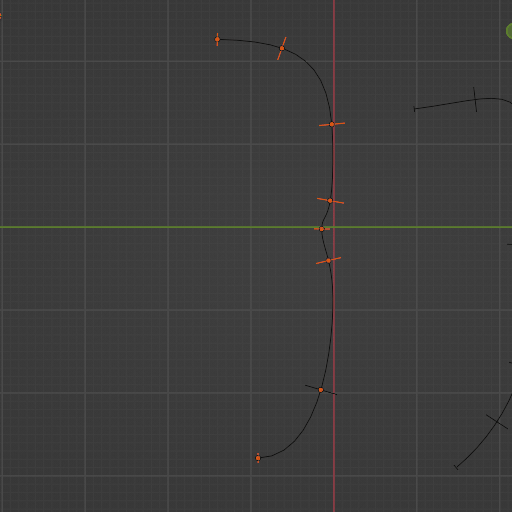
Match Curve Quick Guide
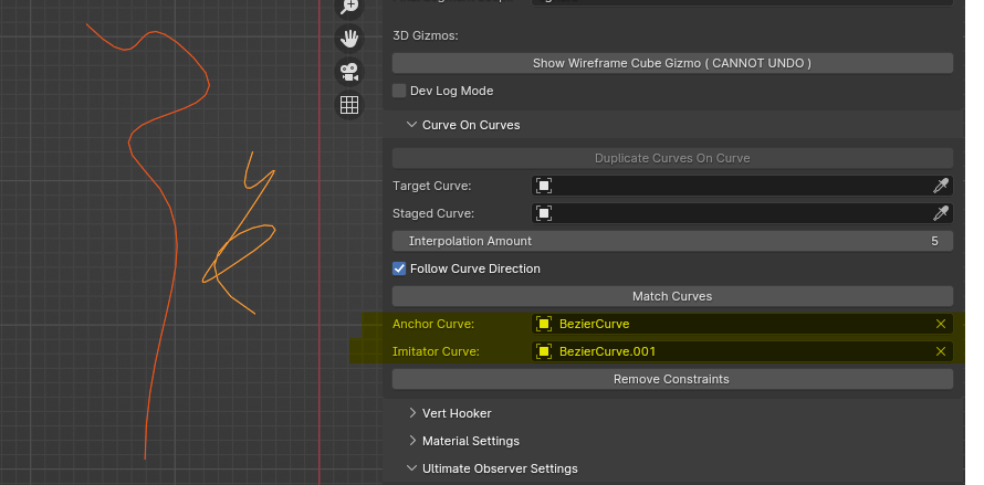
Anchor Curves And Imitator Curves
On the left hand side we have our Anchor Curve and on the right hand side we have our Imitator Curve. The Anchor Curve is responsible for providing all of the relevant information our Imitator Curve will need to copy its properties.
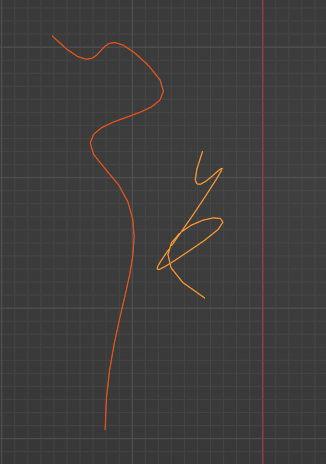
The image above is before we run the Match Curve Operator and below is what occurs after.
After Match Curve Operator:
Although the effect is subtle at times, its outcome is very powerful under the right circumstances. This enables the creator to make edits to the core curve properties in active production without the need to directly modify the data, this is especially useful in cases where the curve being modified has a lot of constraints and other curves associated with it, allowing for a cleaner and more organized workflow.
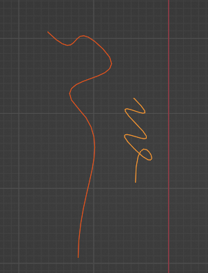
Here we can see that despite having changes in appearance due to the different locations of the control points in the 3D View, the orientation and characteristics of the Anchor Curve were successfully placed upon the Imitator Curve.
Workflow Benefits
The Curves On Curves panel streamlines the modeling process by automating and refining the manipulation of curves, offering benefits such as:
- Efficiency: Significantly reduces the time required to create complex, curve-based structures.
- Precision: Ensures accurate alignment and distribution of curves, improving the overall quality of the model.
- Flexibility: Offers a range of settings to achieve various artistic and technical outcomes, accommodating a wide spectrum of design needs.
Conclusion
The Curves On Curves panel is a powerful addition to the Retro3D Toolkit, designed to enhance your creative workflow in Blender. By leveraging these tools, you can achieve sophisticated curve manipulations with ease, bringing a new level of detail and complexity to your retro-inspired 3D projects.
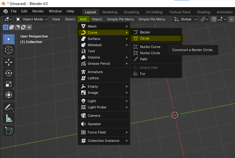
Step By Step Practice:
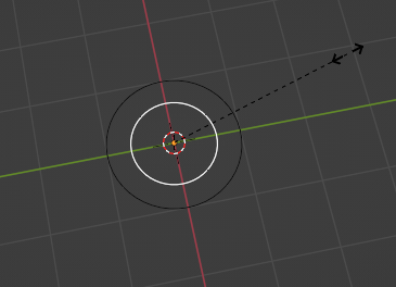
1: Create A Curve, we will use this one as our Target Curve.
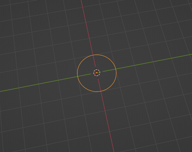
2: You Should now see a curve in the 3D View.
3: Follow step 1 to create a second curve, this will be used for our StagedCurve.
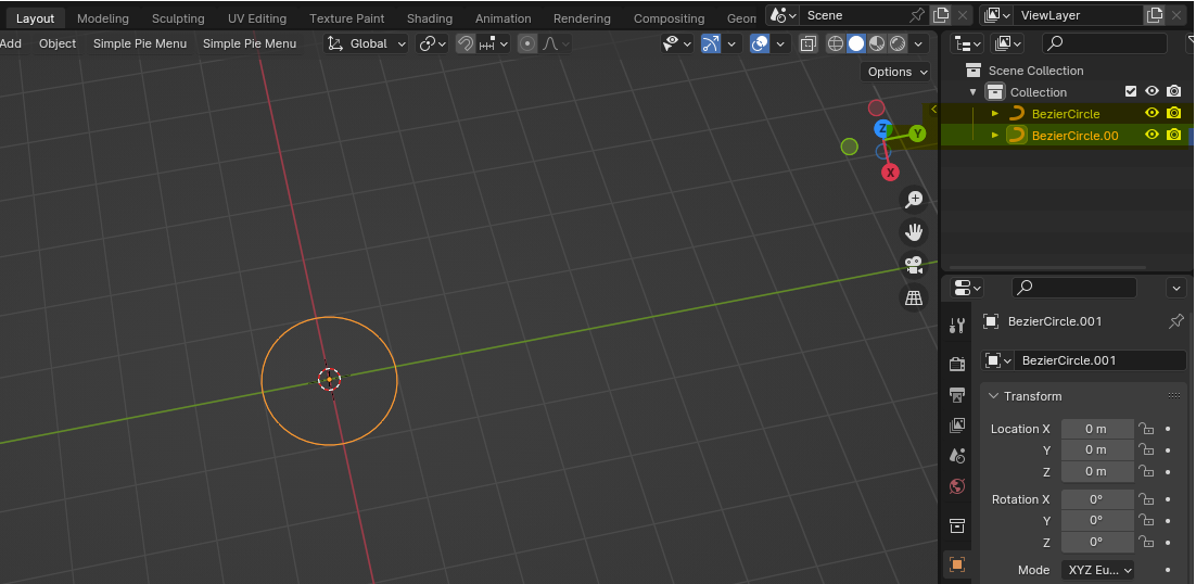
4: Scale down your newly created Staged Curve a bit for better visualization.
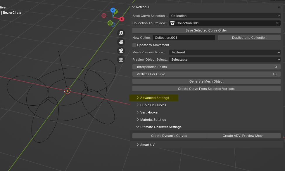
5: If not already open, either click on the small arrow on the edge of the 3D View Port, or click and drag on its edge to expand the toolbars located on the left of the screen.
6: Locate the Retro3D Panel and expand its options
7: Take a Moment to familiarize yourself with the Curves On Curve layout, they are grouped together by relevant data blocks used by the operators. Your property fields should be empty at this point in the tutorial.
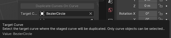
8: Left click the eye dropper icon located on the left hand side of the Target Curve portion of the panel to activate its selection mode, then drag the mouse and select the first curve you created. In our example it is named "BezierCircle".
 9: Your Target Curve property field should now have the object you created from step 1 as its selected object.
10: Repeat the process again, this time taking extra care to ensure that you are using the eye dropper from the Staged Curve property of the panel this time. In our tutorial the object you are trying to select is "BezierCircle.001".
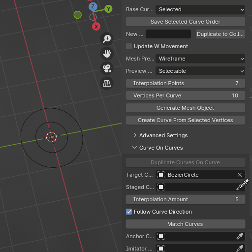
11: Highlighted is the interpolation amount area of the panel, For our example we are going to use an Interpolation Amount of 5.
12: Click on the Duplicate Curves On Curves operator button to see the process begin!
13: Nice! Now we have our perfectly placed curves on curves and can begin other aspects of our mesh generation process!
14: Select the core curve to easily move and control the curves that were placed upon it.
15: Congrats! You have successfully placed your curves on curves! For educational purposes, we will quickly wrap this up and get this generated into a mesh.
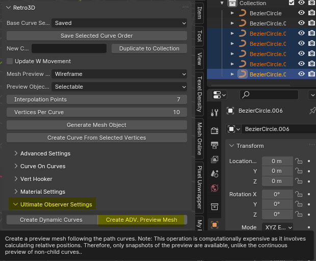
16: In any event, we will need to process our curves to work with our mesh generation system. To begin, ensure that you hold down left click, and then select the curves you wish to use.
Note: THE ORDER IN WHICH YOU SELECT THE CURVES DETERMINES ITS CREATION PROCESS, BE VERY MINDFUL OF HOW THESE ARE STACKED WHEN CREATING
Note: THE ORDER IN WHICH YOU SELECT THE CURVES DETERMINES ITS CREATION PROCESS, BE VERY MINDFUL OF HOW THESE ARE STACKED WHEN CREATING
This is the case for every single curvemesher operation with the exception of proximity based operators. Please refer to the documentation for further details. The mesh generation system we employed here specifically constructs the mesh from the curves in the order they are assigned to your collections or saved instances. If there were any takeaway from all of this, please be mindful of curve order.
17: Save the selection of the curves.
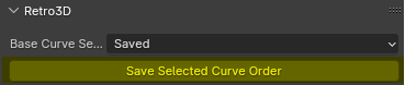
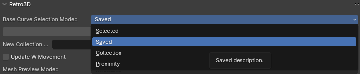
18: You have other options for the mesh generation process, but for now and simplicity's sake, we are going to use the "Saved" option, which is the current order of the curves that were selected prior to being saved.
19: This is a special and more intense utility for mesh generation, we will use the "Create ADV. Preview Mesh" option located in the "Ultimate Observer" panel. That we will cover in another document which also uses near exclusively curves on curves.
If you haven't already, familiarize yourself with the Final Loop Segment Options in the Advanced Settings portion of the documentation for further details.
If not already open select the advanced settings drop down panel to expand the options.
Pick whichever ones you prefer we will show both below so don't worry about which one you start with.
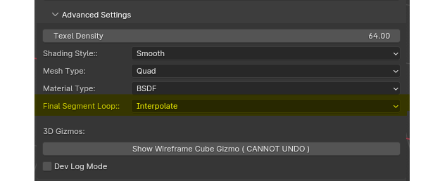
As already mentioned in the Final Loop Segment Options part of the documentation, our setting determines one of two outcomes.
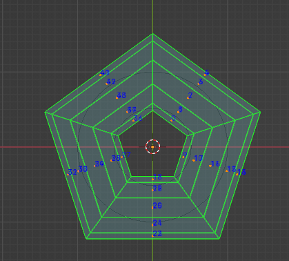
Interpolate
This will cause our mesh generation system to treat the stack of curves as "connected" or forming a circle, this is useful however likely uncommon.
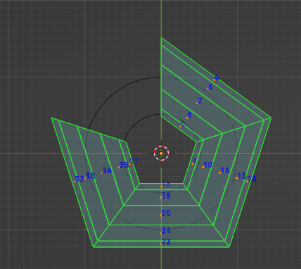
Ignore
This is the most common approach when generating the mesh from the curve data present in your curve stack. This will treat the stack of curves simply as a stack of curves with no looping logic.
From here there are near endless ways one can modify curves and the resulting mesh that is generated. That far exceeds the scope of this documentation. Congrats! You are one step closer to mastery!
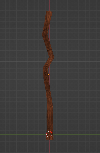
Step By Step Practice 2: Mage Staff
Since you have been following along, this time we will go over quickly the overview of how simple this can be once you have established familiarity.
Start with a simple Anchor Curve and also a Target Curve. Highly recommended to establish a base asset library of common curves you find yourself using so you can simply drag and drop.
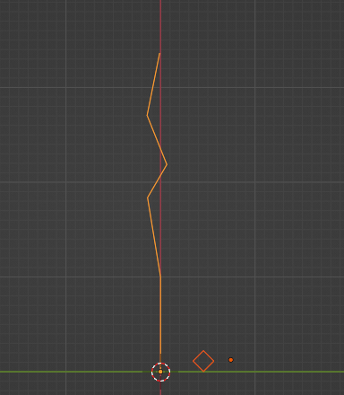
Interpolation of the Target Curve is then propagated along the Anchor Curve path based on its Interpolation Amount.
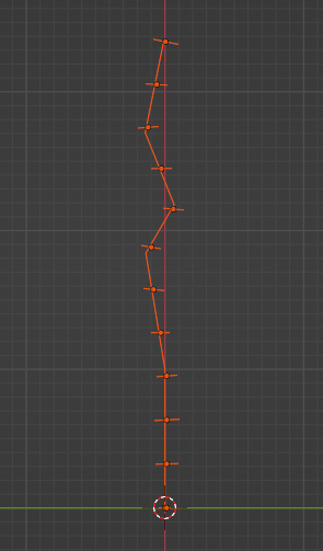
The system then generates the mesh based on its mesh type that can be established in the advanced settings panel.
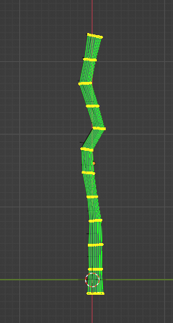
Texture the object to your hearts content. This staff was a very quick example. More intricate tutorials will be available at a later date (humanoids).